Ludlow List List 75-0 & 90-0 Hydrants
Taken from a Ludlow catalog
Fire Hydrants are iron body, bronze mounted for 150-lb water working pressure,
tested at 300-lb hydrostatic pressure.
Cast Iron Parts
Hydrant bottom, connecting pipe, head, packing dome and gate as well as nozzle
cap, umbrella operating nut are made of a special Ludlow-developed cast iron.
Bronze Trim
Seat ring, wedge nut, sleeve, nozzles, gate fastenings and the all-bronze drip
assembly are made of hard, non-galling, low zinc bronze.
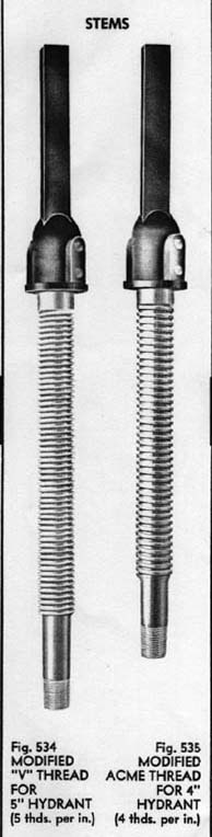
Stem
Threaded portion is of a 90,000-lb tensile strength rolled Everdur bar stock, joined to the
rugged upper portion by a forged coupling.
Gate & Drip Rubbers
Long life, Ludlow-developed rubber seats, are readily replaceable no matter how infrequently
required, as they are secured by non corrodible, all-bronze fastenings.
Locking Device
A rugged Everdur forging in conjunction with a high strength manganese bronze
casting provide a non-galling ball and socket contact surface.
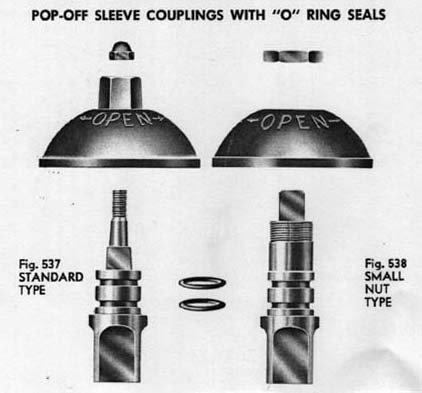
"O" Seals
Special synthetic rubber compound, tested and laboratory-proved superior for fire hydrant service.
"O" Ring Lubricant
Long-life, special, water resistant molybdenum disulfide base compound that "stays put"
and eliminates the need for additional lubrication during the life of the ring.
Bolts and Nuts
Quality controlled steel; rustproofed after threading
Dome Nuts
Rustproofed Elastic Stop Nuts
Construction Details for list 75-0 and list 90-0 post hydrants
List 75-0 Upper Barrel Hydrant Construction Details
List 75-0 Lower Barrel Hydrant Construction Details
List 90-0 Upper Barrel Hydrant Construction Details
List 90-0 Lower barrel Hydrant Construction Details
Actual Images of parts of List 90 Stuffing Box Model
Recommendations for inspecting and servicing
General Disassembly for Inspection
1. Turn off water at secondary gate valve
2. Turn hydrant to partially open position
3. Disassemble 4 dome nuts
4. Remove dome assembly as a unit
5. Lift out complete internal working parts as a unit
With the parts above ground, the operating difficulty can be quickly corrected, without new parts in most cases, by simply removing the obstruction.
Hydrants which are frequently operated, and those in normal operation for periods of 10 to 15 years, can usually be returned to original shut-off efficiency by replacing the rubber seats of the main and drip valves.
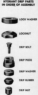
Drip Rubber Replacement - Refer to Drip Assembly
1. Remove stem and gate assembly from hydrant (as for general disassembly).
2. Hold drip washer with pipe wrench and turn bronze drip nut counter-clockwise with Ludlow drip nut wrench or small pipe wrench and disassemble.
3. Replace drip rubber, reassemble nut and tighten to point where rubber starts to deform. Do not overtighten.
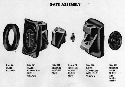
Gate Rubber Replacement
1. Remove stem and gate assmebly from hydrant (as for general disassembly)
2. Hold square stem from turning and turn bronze drip piece with open end wrench counterclockwise to remove drip assembly.
3. Turn lock nut counter-clockwise to disassemble and remove lock washer.
4. Rotate gate assembly on stem to disassemble.
5. Lift out wedge nut
6. Turn gate plate nut counter-clockwise with gate plate wrench to disassemble.
7. Tap exopsed stud of gate plate sharply with wood block to disassemble, using care not to damage gate plate leather.
8. Replace gate rubber and reassemble gate.
9. Reassemble gate and wedge nut on stem.
10. Reassemble gate lockwasher and turn locknut on stem to end of thread.
11. Turn drip assembly on stem and tighten securely against locknut.
12. Check for free rotation of drip rubber assembly.
Additional Hydrant Part Images
Stems for both List 75-0 and List 90-0
Operating nut assemblies for List 75-0 and List 90-0
Back to Hydrant Technical Information Resource
Unless otherwise noted, all contents of these WWW pages © 1996-99, FireHydrant.org
This site designed and maintained by JikTek
|