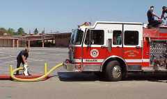
- The first arriving engine makes a standard steamer hookup to the
hydrant.
(Attempts should be made not to obstruct access to the hydrant by a second
engine.)
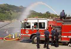
- The first arriving engine fulfills its tactical objectives.
- The second arriving engine takes a position and makes a LDH suction
hookup to the 2˝" hydrant outlet.
- The second arriving engine fulfills its tactical objectives.
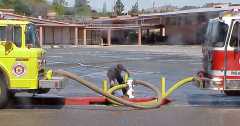
- If the residual pressure coming in to the second engine falls off
too sharply (approaches or drops below 10 p.s.i.) a compensating line
should be connected to the pony suction connections of the two engines.
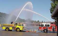
Trial Results:
The first arriving engine had no difficulty maintaining residual pressure.
(It never dropped below 30 p.s.i.) The second arriving engine dropped below
10 p.s.i. residual pressure but this weakness would be adequately corrected by
introducing the compensation line.
Key Points:
It would be a rare occurrence for two engines to each flow 1000 GPM during a
two pumper hookup, however we know that it can be done.
Once pumping operations have started, a compensation line should always
be connected between the auxilliary suction inlets of both engines.
The concept here is to share intake supply, not mix intake and
discharge connections. The excess residual intake pressure at one engine will
seek balance with the lower intake pressure of the second engine.
Engineers should communicate with each other when significant flow changes take
place.
|