Join our Email List | Collectors Club | Hydrant Links | We Need Your Help | Contact Us
|
|
Join our Email List | Collectors Club | Hydrant Links | We Need Your Help | Contact Us |
|
We would be delighted to try and obtain an answer to any questions you might have regarding fire hydrants, whether of a technical or general nature. Below are recent questions and answers from the FireHydrant.org mailbag. If you have a question, Email Us. |
|
#19 - What is the definition of a wharf head hydrant, what sets it apart? Why are they specified? A wharf head by definition is a hydrant which connects directly to a wet riser. On wharves and piers there is no practical ability to install a "hydrant bury" complete with foot valves and thrust blocks and the name has stuck to all hydrants that are basically just hydrant tops screwed onto vertical pipes. Wharf head hydrants come in all sorts of riser sizes up to 6" in diameter. Their common characteristic is that they literally thread onto a piece of iron pipe. The majority of wharf heads thread onto 4" pipe and have a single operating nut at the top of the hydrant such as the Greenburg wharf head. Out here in more temperate climates it was fairly common for these heads to be used in the 40s and 50s in residential neighborhoods that were served by only 4" water mains. The installation of a hydrant merely required the contractor to install a tee, street valve (for knockdowns), and run some pipe to the side of the road and bring it up with an elbow. The wharf heads were typically with a single or double 2˝" outlets. To lower the costs of installations in modern subdivisions a few manufacturers have produced wet barrel heads which can thread directly onto 6" pipe risers which they have marketed as "residential wharf heads." My personal opinion is that the local agency is better off requiring a bolt down hydrant since it makes repair and replacement so much simpler in event of a knockdown. ":O) Willis Lamm,
|
|
#20 - We are in the planning stages of a dry hydrant system and we have run into a few technical difficulties and were wondering if you could be of some assistance. The plan is for a 140 foot horizontal run of 8 inch PVC pipe with a verticle lift of 6 feet. Almost 110 feet will be submerged. There will be 5 (five) 45° and 1 (one) 90° in the system. The Department of Fish and Game has mandated that the holes in the strainer are no larger than 3/32-inch (0.09375) and that the water velocity at the screen/water interface may not exceed 0.4 feet per second (fps) when the pump is operating. So this is what we have to deal with and these are the questions: 1. Can we draft 500 to 1000 gpm using a class A pumper? 2. What do we have to change to make it happen? Thank you for your attention to this. Good questions, and thanks for sending them this way. I have some folks chewing on a couple of items, but this is the summary for now. The lift, the length of the pull, the angle changes, and the quantity flow desired are no problem. You can actually pull 1,000 GPM out of a five inch pipe with a good pump. The length of the horizontal pipe is no problem, as long as the water will return to a static level near the vertical draw and the pull does not exceed the maximum rating for your pumps. The only factor we can see right now that may be a problem, is the size of the orifices in the intake screen. This can be compensated for by changing the total surface area of the intake. I am concerned about freezing, since this will be in Alaska. Is this going to be a year 'round hydrant? If so, six feet of depth may not be adequate. Wouldn't be half far enough for the Interior. I am also curious about all the angle changes. Are you having to work around obstacles? We are not so sure about the velocity issues, since we are not mechanical or hydraulic engineers, but someone at the University of Alaska should be able to address these. Another suggestion. Contact an Operations person at Nikiski Fire. Billy Harris was the Chief there and he was a wizard at dry hydrant issues. I believe Billy is retired now, but his knowledge may have been passed on or recorded there. Can you forward a drawing of your planned installation? Will send more just as soon as possible. Good luck. Jerry Hanson |
|
#21 - I'm looking for a manufacturer of bags made to cover fire hydrants that have been installed, but are not yet in service. It is my understanding that hydrants that are not in service need to be covered by such a bag. We would like to call them out in our construction specifications for a site development project that we are currently working on. Any assistance that you can give me in locating any such bags would be greatly appreciated. Vinyl out of service bags are pretty pricey. We specify that hydrants not in service are to be securely covered by a burlap sack or other opaque material (e.g., inverted black garbage bag) until such time as they are fully pressurized and available for service. Our practice is to also flow test and color code hydrants as soon as they are in service. This provides two benefits. First, if there is a choked valve or obstruction supplying a hydrant, it can be detected and flagged for correction while the contractor is in the area. Secondly, companies rolling into a construction area that find one or more hydrants that do not have NFPA flow markings are visually alerted to check the hydrant (open it without hoses attached) before committing to a fire control operation using that hydrant. Engine companies should also carry "out of service" rings that can be placed behind the 2˝" caps so if they find an uncovered hydrant that is dead or come across one with traffic damage or other problems, they can be clearly tagged as O.O.S. until placed in service or repaired. If you still want special out of service bags, your best source will probably be W. S. Darley and Co., Melrose Park, IL. Their on-line address is http://www.edarley.com . (Their on-line catalog is hard to search so just email them and tell them what you want.) Hope this info helps. If you're still stuck, please email me. ":O) Willis Lamm,
|
|
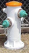
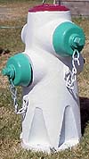
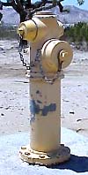
#22 - Good day, Hi, my name is LTA Zaid from the Singapore Civil Defence Force. Currently, myself and my team members are embarking on a project to explore the possibility of re-designing our existing Double Pillar Hydrant (DPH). We have actually come up with a new design. We would appreciate if you could provide us with your frank comments on our proposed design. a. Is it feasible to have the control valve at the hydrant outlet? b. Will there be a possibility of water leakage? c. Will there be any corrosion problem if the hydrants are constantly charged with water? d. Do you have any other remarks for our hydrant proposal? 5. Your feedback will be greatly appreciated and we hope to hear from you soon. Thank you and regards. Dear LTA Zaid, Considering the mild weather in Singapore, your concept regarding keeping the hydrant barrel charged is very sound and should result in improved flows as well as more expedient taking of water by fire personnel. I might propose a simpler method of controlling the discharges which absolutely would not leak and would provide complete and efficient independent control of each nozzle outlet. Instead of placing each outlet along the same plane in opposite directions of each other, consider placing one outlet above the other and at a 90 degree angle. By doing this you can install a compression valve behind each outlet which is controlled from the opposite side of the hydrant. I will try to explain this so that it makes some sense. Each discharge outlet nozzle would thread into the hydrant body. The shank of the nozzle (facing inward to the barrel) would have a machined surface that the compression valve would seat against. Directly behind each nozzle outlet, on the opposite side of the body, would be an equally placed threaded opening. In this opening a valve stem guide would be attached. The compression valve would then be installed horizontally, transcecting the body, where it would seat against the nozzle opening preventing any discharge of water, or it would be retracted when the valve stem was turned open allowing full bore discharge through the nozzle opening. Through such a configuration the hydrant could be rapidly opened when a hose is attached, then a second hose could be attached and charged independently without having to shut down the hydrant. By continuing to have the main valve below ground, the hydrant could be shut down at the street for purposes of servicing the valves or making repairs, otherwise it would stay "wet" at all times. I have attached some photographs of California hydrants that use a similar design. The first two are of a cast iron hydrant with bolt-on flange and the third is of a brass hydrant. All of these hydrants are cast with a 6" inside diameter for maximum efficiency.
|
|
Photo #1: 1947 model "wet barrel" designed by the East Bay
Municipal Utility District
Photo #2: 1969 version, designed by the East Bay Municipal Utility District. (The design of gussets integral with the body provide superior strength against vehicle damage.) Photo #3: James Jones Co. brass hydrant with 6" thread-on body on a 6" steel pipe riser. |
 |
 |
 |
|
":O) Willis Lamm,
|
|
#23 - I just got an email from a person in North Dakota inquiring about fire hydrants that freeze up because the drains are lower than the water table. I have never really had to deal with this type of question so I was wondering if anybody can supply some information about this topic. I know that manufacturers have tried some different methods of making hydrants with above ground drains, etc, but just curious as to what the current practice is on this matter. Drain holes are a pain in colder climates, and they also create a cross connection situation where ground water can be given an opportunity to get into the potable water supply. We now specify that all of our hydrants are to be plugged and we pump them out after they are used. We also have a big job ahead of us as we endeavour to identify which hydrants still have drains and need to be plugged. In the meantime we have to continue to steam frozen hydrants and remove the water. John Clack
|
|
#24 - I am trying to model a water distribution system, and need to know what loss I can expect to get going through the hydrant. These are 5 1/4" barrels with a 4" outlet. Be very, very careful with this one - Manufacturers quote only the friction loss thru- the hydrant, not including the change in head due to change in velocity (the flow thru- a 6" (nominal but probably larger if the pipe is ductile iron) inlet is sqeezed down to 4") and the change in head due to change in elevation (the inlet is about 6feet below the outlet) - They certainly don't include the head loss of the sudden opening that would be the case were the hydrant discharging directly to the atmosphere. The answer to the question you asked is "a modern fire hydrant has a friction head loss of about 2.5 to 3.0 psi when 1000 GPM(US) is flowing thru- a 5 1/4" hydrant with a 6" inlet and a 4" outlet." - If the hydrant is an "old" hydrant - say, pre 1980 - factor in a friction headloss of about 3.5 to 5.0psi under similar circumstances. When you are setting up your model use the above data to construct a factor for your equation(s). - The head loss increases almost directly as the velocity squared. If a hose is connected to the hydrant it is safe to ignore the friction loss of the hydrant. When considering a system originating at the pumping station and terminating at the nozzle of a hose the hydrant isn't much of a factor at all. Louie Carl |
|
|
|
|
| Unless otherwise noted, all contents of these WWW pages © FireHydrant.org |